Blog · Structured light ·
Painting a number onto the world with Gray code
You cannot search for where a projector pixel lands in a camera image: you label every column and row with a binary number and project the bits, one plane at a time. Why plain binary breaks at the boundaries, Gray code does not, and a widget that turns your screen into the projector.
- interactive
- structured-light
- computer-vision
- gray-code
This is the front door to a small structured-light scanner I built out of a projector, a DSLR and a Kinect for comparison. I also wrote the whole thing up as a university project report, thirty-six pages of it, which I never got around to exporting out of page images into anything more citable, so where it says something worth keeping I’ll quote it directly rather than point at a page number. This post is the part that needs no hardware at all: how you get a camera and a projector to agree on where a point in the world is, using nothing but light and arithmetic.
One eye that emits instead of receives
A stereo camera pair finds correspondences by matching: the same corner of the same object, seen from two eyes, triangulated. A projector-camera pair could work the same way, except one of the “eyes” doesn’t receive light, it emits it. You can’t feature-match a projector pixel against a photograph, because a plain white square of light has no texture to match. Instead you make the projector tell the camera which pixel it is.
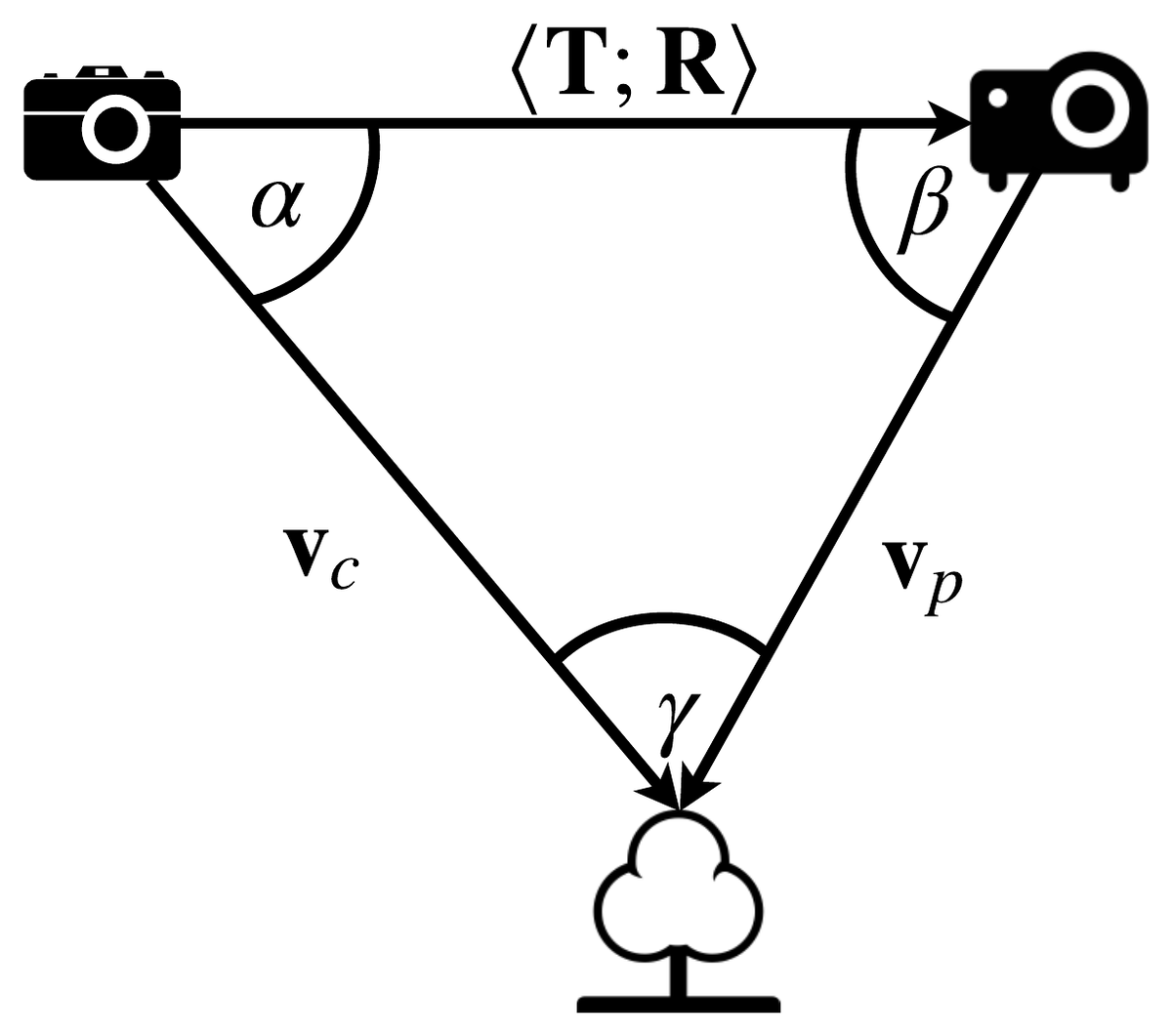
and are the rays from camera and projector to the same object point, the rigid transform between them (found by calibrating the two devices against each other, a later post).
Once a camera ray and a projector ray are known to be looking at the same point, the geometry is just a triangle. The angles come from the dot product,
and once and are known, and the sine rule gives the distance to the point along the camera ray:
That’s the whole reconstruction, and it’s genuinely three lines of code, but it needs both rays first, and finding the projector ray is the hard part. This post is entirely about that: how do you know, for a given camera pixel, which column and row of the projector it’s looking at?
Sweep a line, or ask a better question
The obvious answer is to sweep a bright line across the projector, column by column, and photograph each one. If a camera pixel lights up when column 511 is illuminated, that pixel is looking at column 511. It works, and it is completely impractical: a 1024-wide projector needs 1024 photographs, plus another 768 for the rows. The report dismisses this in one line: “this approach is highly inefficient as each pixel row and column should be illuminated separately.”
The better question isn’t “which column is lit right now” but “what binary number is this pixel’s column?”, because a number can be transmitted a few bits at a time, not one value at a time. Convert each column index to binary and project the bits as black/white stripes, most significant first: half the projector lit for the top bit, alternating quarters for the next, alternating eighths after that. A camera photographing all images gets a 0 or 1 out of each one for a given pixel, and those bits reassemble into the column index. Ten photos identify one of 1024 columns instead of 1024 photos identifying one column each.
| Strategy | Photos for a 640 px axis | The catch |
|---|---|---|
| Sweep a line | 640 | one photo per column; dead on arrival at projector resolution |
| Binary bit-planes | 10 | fast, but boundaries can flip several bits at once (below) |
| Gray code bit-planes | 10 (+10 inverse) | same photo count as binary; a boundary only ever moves one bit |
| Colour-coded single pattern | 1 | breaks on objects that already have that colour |
| Structured single pattern (Kinect) | 1 | fastest, but less complete: needs a neighbourhood window to decode, so it struggles near edges |
(The report covers the last two: colour patterns “reduces the number of objects which can be accurately scanned… as objects containing certain colours can affect its performance,” and the Kinect’s own approach “is able to scan objects much faster than the Gray code approach. However, this approach may be less complete, especially close to edges of an object, as it relies on regions of the pattern to be identified.”)
Where plain binary breaks
Binary bit-planes have an ugly property at the boundaries. Go from column 511 to column 512,
0111111111 to 1000000000, and every single bit flips at once. In the real world that
boundary is never a knife-edge in a photograph: focus blur, projector lensing and camera noise
smear it over a few pixels, and any one bit read wrong there can throw the decoded index off by
half the projector’s width, not by one column.
Gray code fixes this by construction: consecutive values differ in exactly one bit. The report states the property plainly: “any errors in the reconstruction of the bits are more likely to only influence the result by a minor amount as opposed to a large amount. Furthermore, when using this pattern, the highest frequency component is 2 pixels wide as opposed to the 1-pixel wide pattern produced by the binary sequence.” That second point matters as much as the first: the finest Gray stripe is two projector pixels wide, so it’s still resolvable through a camera lens that has blurred the finest binary stripe into mush.
The two stacks look almost identical and decode completely differently. These are the report’s own figures, generated for a 640 px wide projector, ten images each, most significant bit at the top:
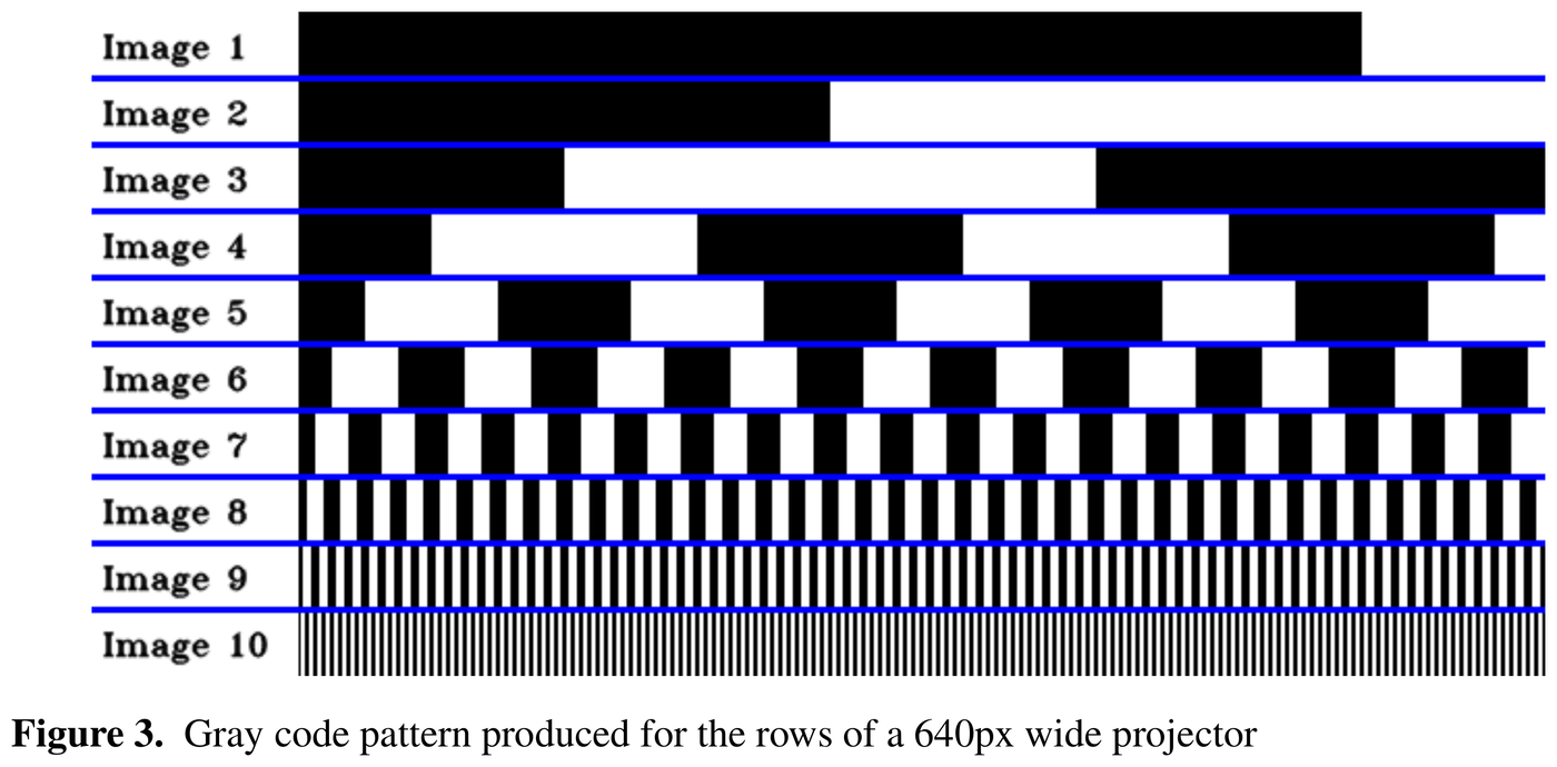
The Gray code pattern for the rows (here: columns) of a 640 px projector, straight from the report.
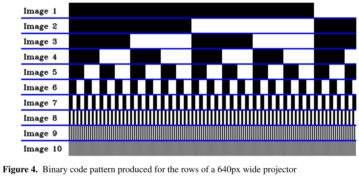
The equivalent plain binary pattern. Notice image 10’s stripe width: one pixel, against Gray’s two.
Converting an index to Gray code is one XOR:
Here are the first sixteen, re-sorted by value so the one-bit-at-a-time property is easy to see reading down each column:
| Value | Gray code | Value | Gray code |
|---|---|---|---|
| 0 | 0000 | 8 | 1100 |
| 1 | 0001 | 9 | 1101 |
| 2 | 0011 | 10 | 1111 |
| 3 | 0010 | 11 | 1110 |
| 4 | 0110 | 12 | 1010 |
| 5 | 0111 | 13 | 1011 |
| 6 | 0101 | 14 | 1001 |
| 7 | 0100 | 15 | 1000 |
Decoding back to a plain index is the useful direction: the camera can only ever recover Gray bits, one per photographed plane, and it’s a cascading XOR rather than a lookup table:
Four shifts, independent of how many bits are actually in use: it decodes a full 16-bit word whether the projector is 64 px or 1920 px wide, and the unused high bits just come out zero. The C++ decoder is a direct transliteration:
uint16_t getGrayCode(uint16_t gray)
{
	gray ^= (gray>>8);
	gray ^= (gray>>4);
	gray ^= (gray>>2);
	gray ^= (gray>>1);
	return gray;
}
Why every pattern gets projected twice
Neither figure above is the whole story: the scanner also projects the inverse of every plane, 42 exposures per scan, not 20 (10 column planes + 10 inverses, 10 row planes + 10 inverses, plus a fully black and a fully white reference frame, the exact order is a section down). The reason is optical, not algorithmic, and the report puts it plainly:
Later, looking at the actual photographs, the same effect shows up as measured fact rather than theory:
A single fixed brightness threshold (say, “lit if above 128”) has no way to know that a given pixel’s local lit-to-unlit crossover sits at 140 rather than 110, every pixel’s glass, coating and defocus is slightly different. Photographing the inverse too means every pixel gets its own threshold for free: whichever exposure reads brighter, that’s the state, decided per pixel rather than guessed globally. (The actual decision rule is a five-way case split against a direct/global light separation, not a simple compare: that’s the next post in this series.)
The code that makes the stripes
The entire pattern generator is two small classes, and it’s genuinely all the algorithm there is: no library does bit-plane unpacking for you:
class GrayImage:
    def __init__(self, width=1024, height=768):
        self.width = width
        self.height = height
        max_dim = max(self.width, self.height)
        self.num_bits = int(ceil(np.log2(max_dim)))
        grayCodes = np.arange(max_dim, dtype=np.uint16)
        grayCodes = (grayCodes >> 1) ^ grayCodes
        grayCodes.byteswap(inplace=True)
        self.grayCodes = np.unpackbits(grayCodes.view(dtype=np.uint8)).reshape((-1, 16))[:, 16-self.num_bits:]*255
        self.invGrayCodes = 255 - self.grayCodes
(grayCodes >> 1) ^ grayCodes is the same Gray-code formula from earlier, applied to every index
at once; np.unpackbits after a byteswap turns each 16-bit code into its individual bits, sliced
down to just the num_bits that matter and scaled to 0/255 so the array is the image.
BinaryImage, the plain-binary counterpart, is identical except it skips the Gray transform,
which is exactly what makes it fragile. A short driver script calls both classes and writes out
the two contact sheets above, one row per bit plane, in about thirty lines.
Forty-two frames, in this order
Both axes get coded, because one number is not a correspondence. A camera pixel that decodes the column planes knows it is looking at projector column 611; that pins it to a line in the projector, not a point. Decode the row planes too and you have (611, 284), a single projector pixel, and with it the second ray the triangle needs. So the stack is run twice: once with the stripes running vertically, numbering the columns, and once horizontally, numbering the rows.
The pattern generator’s iterator method is where the whole capture order lives, and it is worth reading closely because it also fixes the filenames the decoder will look for later (one debug print trimmed):
    def getIterator(self):
        self.imageOut[:,:] = 0
        yield "b", self.imageOut
        self.imageOut[:,:] = 255
        yield "w", self.imageOut
        for i in range(self.num_bits):
            self.imageOut[:] = self.grayCodes[:, i]
            yield "h"+str(i), self.imageOut

            self.imageOut[:] = self.invGrayCodes[:, i]
            yield "ih"+str(i), self.imageOut

            self.imageOut[:] = self.grayCodes[:self.height, i, None]
            yield "v"+str(i), self.imageOut

            self.imageOut[:] = self.invGrayCodes[:self.height, i, None]
            yield "iv"+str(i), self.imageOut
Black, white, then for each bit plane four frames: pattern and inverse for one axis, pattern and inverse for the other. Ten bit planes for a 1024-wide projector, so .
The two slicing expressions are the whole difference between the axes, and the naming is the
reverse of what you might guess. self.grayCodes[:, i] is a row vector as long as the image is
wide, broadcast down every scanline: the value varies horizontally, so the stripes stand
vertically and the frame encodes a column index. That one is called h.
self.grayCodes[:self.height, i, None] is a column vector as tall as the image, broadcast across
every column: the value varies vertically, the stripes lie horizontally, it encodes a row
index, and it is called v. The letters name the direction the index runs, not the direction the
stripes run.
The decoder reads them straight back by those names:
hImgs[i] = cv::imread(currentDir + "/h" + std::to_string(i) + imgFormat, cv::IMREAD_GRAYSCALE);
vImgs[i] = cv::imread(currentDir + "/v" + std::to_string(i) + imgFormat, cv::IMREAD_GRAYSCALE);
ihImgs[i] = cv::imread(currentDir + "/ih" + std::to_string(i) + imgFormat, cv::IMREAD_GRAYSCALE);
ivImgs[i] = cv::imread(currentDir + "/iv" + std::to_string(i) + imgFormat, cv::IMREAD_GRAYSCALE);
...
bImg = cv::imread(currentDir + "/b" + imgFormat, cv::IMREAD_GRAYSCALE);
wImg = cv::imread(currentDir + "/w" + imgFormat, cv::IMREAD_GRAYSCALE);
So a complete scan on disk is b, w, h0…h9, ih0…ih9, v0…v9, iv0…iv9 in one
directory, in whatever image format the capture used (.jpg by default, because that is what
the DSLR wrote). Everything downstream in this series takes exactly that directory of frames.
Try it: the stripe explorer
The widget below regenerates the exact bit-plane stack from GrayImage/BinaryImage for an
axis length you choose, toggling live between Gray and binary and between the two orientations,
vertical stripes for the column planes (h0…h9), horizontal stripes for the row planes
(v0…v9). Scrub an index to see its binary and Gray code and which planes are lit for it. The
bit-flip panel picks one plane and simulates a misread of it: at the plane’s actual stripe
boundary a Gray misread moves the decoded index by exactly one; a misread of the same plane read
as plain binary moves it by exactly (up to 512, for the most significant bit
of a 1024-wide pattern), regardless of where in the image it happens.
And then, because the whole point of these images is to be thrown at a wall, the same widget will project them. More on that below the panel.
With JavaScript on, this becomes an interactive bit-plane stack: choose an axis length, swap between vertical and horizontal stripes, toggle Gray versus binary, scrub an index, and flip a bit to see how far the decoded answer moves under each scheme, plus a full-screen projector mode and a download of the whole pattern set as PNGs.
Use it as a projector
The original rig used two small scripts for this: one put an OpenCV window into full screen and walked the iterator, one frame per keypress, while the other fired the DSLR between them. A laptop screen stood in for the projector the whole time I was writing it, and that works well enough that the widget above now does the same job with the Fullscreen API. Project full screen blanks the page; the first page you land on is the settings, and from there:
| Key | Does |
|---|---|
→ or Space | next frame |
← or Backspace | previous frame |
Esc or X | leave full screen |
Touch works too: tap the right half of the screen for the next frame, the left half for the
previous. Nothing advances on its own unless you tick Auto-advance, which is off by default
and stays off under prefers-reduced-motion; the real rig was gated by the camera’s shutter, not
by a timer, so a dwell time is a convenience rather than a fidelity feature.
Two of the settings matter more than the rest. Match the screen generates each frame at the
display’s actual innerWidth × innerHeight in device pixels and regenerates on resize, so one
projector pixel is one screen pixel and the bit-plane count follows the real width, the same
thing GrayImage()’s defaults are doing when they say 1024 × 768. Turn it off and you can pin the
pattern to a specific resolution instead, letterboxed on black. Axes picks columns only, rows
only, or both in the rig’s interleaved order.
To actually try it: put the page in full screen on a laptop, point a phone camera at the screen from off to one side, and step through with the arrow keys, taking one photo per frame. Hold a book or a mug in the beam and the stripes bend around it, that bend is the depth, and the next two posts in this series are about measuring it. The small frame index in the bottom corner is there so you can tell from the photographs which frame you were on; it is mine, not the original rig’s, and it does overwrite a few hundred pixels of the pattern, so switch it off if you intend to decode that corner.
Download patterns (.zip) writes the whole set out as PNGs at the chosen resolution, named
b.png, w.png, h0.png, ih0.png, v0.png, iv0.png, … exactly as getIterator yields them
and the cv::imread calls above expect them, plus a small JSON file recording the size, the bit
count and the order. Unzip into one directory and the C++ decoder shown earlier will read it
straight off disk, no renaming needed. The archive is written in the browser by about sixty lines
of stored-mode ZIP: local file headers, a central directory, an end-of-central-directory record
and a CRC-32 table. PNG is already deflated, so storing costs nothing and saves shipping a
compressor to do it twice.
What this buys the rest of the series
Forty-two photographs and two small functions are enough to give every camera pixel a candidate projector column and row, assuming the camera can reliably decide whether each plane was lit at that pixel in the first place, which turns out to be its own hard problem once shadows, glare and an out-of-focus wall are involved. Building the actual capture rig (projector, camera, and enough synchronisation to get all forty-two frames without touching anything) is next; deciding, pixel by pixel, whether a stripe was really lit is the post after that. If you want to run ahead, the ZIP the widget hands you is already the input both of those posts start from.