Blog · Camera geometry ·
Finding a checkerboard, from adaptive threshold to sub-pixel saddle
The structured-light rig calibrates against a ChArUco board with one call to cv2.aruco. Here is what that call actually does, reimplemented independently in Rust: adaptive threshold, Suzuki–Abe contour tracing, a per-quad homography and a Hamming-corrected dictionary decode.
- interactive
- computer-vision
- aruco
- charuco
- contour-tracing
- camera-calibration
- wasm
cv2.findChessboardCorners finds a checkerboard, or it doesn’t. When it doesn’t, you get
nothing: no reason, no partial answer, and no way to ask “did you at least see the left
half of the board?” Post 38 opened that box for a plain
checkerboard: a corner is a saddle point of intensity, one Hessian eigenvalue test finds
every candidate, and four geometric filters clean up the impostors.
This repo doesn’t calibrate against a plain checkerboard, though. It calibrates against a ChArUco board, a checkerboard with a small binary-coded square dropped into every other cell, and the reason is exactly the failure mode above. A plain board is one blob: cover a corner of it, or catch it at a bad angle, and the corner-ordering step (the “find the four extreme corners, walk the edges” trick from post 38) has no way to know which edge it lost. A ChArUco board is dozens of small, independently-readable IDs. Cover half of it and the other half still tells you exactly which squares you’re looking at, because each one says so.
Why ChArUco, in the repo’s own words
The report’s rationale (§4.2.3) is worth having straight, because it’s easy to reach for “ArUco is fancier” and miss the actual argument:
The calibration technique used follows the method suggested by D. Moreno and G. Taubin. First, a known pattern is generated. The usual choice for this is usually either a checkerboard or a grid of circles. The checkerboard provides easy to identify corners, which can be detected to sub-pixel accuracies. An improvement to the checkerboard pattern is known as a ChArUco board. A ChArUco board is a checkerboard pattern which contains ArUco markers in each white block. ArUco markers are square markers which are easy to uniquely identify in an image. Using them with the checkerboard pattern allows one to identify which corners are present in an image.
Two sub-claims are doing the work there: sub-pixel corners (which a plain checkerboard already gives you, that’s post 38) and knowing which corners you found (which it doesn’t). The second one is the actual improvement, and it’s why a partially-covered ChArUco board still calibrates while a partially-covered checkerboard just fails.
The board
The script that generates the board is short enough to quote whole:
dpmm = 40
A4_shape = 210, 280
A4_shape_margin = A4_shape[0]-10, A4_shape[1] - 20
outshape = A4_shape[0]*dpmm, A4_shape[1]*dpmm
desired_block_size_mm = 20
desired_aurco_size_mm = 14
desired_gap_size_mm = 5

blocksx = A4_shape[0]//desired_block_size_mm
blocksy = A4_shape[1]//desired_block_size_mm

aurcoDict = aruco.getPredefinedDictionary(aruco.DICT_4X4_250)
charucoBoard = aruco.CharucoBoard_create(blocksx, blocksy,
                                         desired_block_size_mm,
                                         desired_aurco_size_mm,
                                         aurcoDict)
210 × 280 mm, not the true A4 297 mm: 280 is 14 × 20, so fourteen whole 20 mm rows fit
exactly and there’s 17 mm of margin left over at the bottom rather than a fifteenth
half-row. blocksx, blocksy = 10, 14: ten columns, fourteen rows of 20 mm squares, a
14 mm DICT_4X4_250 marker centred in every other one. That’s (10 × 14) / 2 = 70
marker squares and (10 - 1) × (14 - 1) = 117 interior checkerboard corners, both
numbers the widget’s live readout counts up to.
DICT_4X4_250 means every marker encodes a 4×4 grid of black/white bits, chosen from
OpenCV’s own list of 250 codewords engineered to survive being confused with each other.
The detector below reads that same list, and the geometry above is exact: same block
count, same square size, same marker size, same sheet, and markers in the white squares
with square (0, 0) black, the parity CharucoBoard uses. The “print this board” link
under the widget renders it at true millimetre scale from these numbers, so a sheet
printed from this page is the board BoardInfo.py describes, readable by cv2.aruco as
well as by the widget.
Adaptive threshold
Everything downstream depends on turning grey pixels into “ink” or “not ink,” and a single global threshold can’t do that across an unevenly-lit board: the repo’s own photos have a projector-lit wall behind the board and open shadow in front of it, so one edge of the frame can be twice as bright as the other. OpenCV’s ArUco detector is set up for exactly this:
detectorParams = aruco.DetectorParameters_create()
detectorParams.adaptiveThreshConstant = 5
detectorParams.adaptiveThreshWinSizeMin = 3
detectorParams.adaptiveThreshWinSizeMax = 50
detectorParams.adaptiveThreshWinSizeStep = 2
detectorParams.minMarkerPerimeterRate = 0.01
detectorParams.maxMarkerPerimeterRate = 8
OpenCV actually re-thresholds several times, walking the window size from 3 up to 50
in steps of 2 and pooling candidates across all of them, so a marker that’s the wrong
size for one window still gets caught by another. My Rust (board::adaptive_threshold) thresholds once, at a single window the widget’s
slider controls: a deliberate simplification, so a reader can see what one window buys
you before imagining the multi-pass version.
The threshold itself is the standard “mean minus a constant”: for every pixel, compare it
to the average of its own window × window neighbourhood, marked as foreground (probable
ink) if it’s more than C darker than that local average. Computing that mean naively is
O(window²) per pixel; a running-sum integral image makes it O(1) per pixel regardless
of window size, so the slider stays interactive at any setting:
let mut integral = vec![0.0f64; (w + 1) * (h + 1)];
// ... prefix sums, one pass ...
let mean = box_sum(x0, y0, x1, y1) / area;
out[y * w + x] = if px < mean - c as f64 { 255 } else { 0 };
Drag the window slider small and the board’s own printed line-work starts thresholding against itself (every dark pixel judged only against its immediate, equally-dark neighbours); drag it large and a real shadow gradient across the frame stops being local enough to cancel out. Where the optimum sits depends on how many pixels a marker module covers, which is why both bundled photos default to a 7 px window: the board is far enough from the camera that anything wider starts averaging a module together with its neighbour. The “threshold” stage in the widget below shows exactly this trade-off live.
Suzuki–Abe contour tracing
A binary image full of board::find_contours’s “foreground” pixels doesn’t tell you
where any shape is: you still have to walk each blob’s boundary and turn it into an
ordered list of points. The obvious way is a flood fill per blob; the way OpenCV’s
findContours actually works, and the way board::find_contours reimplements, is one
raster scan that finds every border, including the borders of holes inside a
region, without ever re-visiting a pixel twice.
The trick is a marking scheme. Scanning left-to-right, top-to-bottom, a foreground pixel
with a background pixel immediately to its left starts a new outer border; a
foreground pixel with a background pixel immediately to its right starts a new hole
border. Either way, the border gets a fresh id (NBD, “newly found border”) and is
traced with an 8-connected walk: from the current border pixel, search its neighbours
counter-clockwise, starting just past the direction you arrived from, for the next
foreground pixel. Each pixel visited gets written with ±NBD: positive if it’s a real
interior point of the region, negative if its immediate east neighbour is background
(meaning a later raster-scan visit to it must not mistake it for the start of yet
another border). That marking is the entire reason one pass suffices: by the time the
scan reaches a pixel again, its value already says whether it’s already spoken for.
// 3.3: counter-clockwise search from just past the direction to (prev_x, prev_y).
let from_dir = dir_index(prev_x - cur_x, prev_y - cur_y);
for k in 1..=8 {
    let d = ((from_dir as i32 - k as i32).rem_euclid(8)) as usize;
    // ... first nonzero neighbour wins ...
}
// 3.4: the *fixed* east neighbour decides the sign, not the one the search found.
if get(&f, cur_x + 1, cur_y) == 0 { f[idx] = -nbd; }
I don’t track the parent/hierarchy half of the paper (which border is a hole inside which outer border): the quad search below only needs the shapes, not their nesting, so this is a real but intentional subset of the full algorithm.
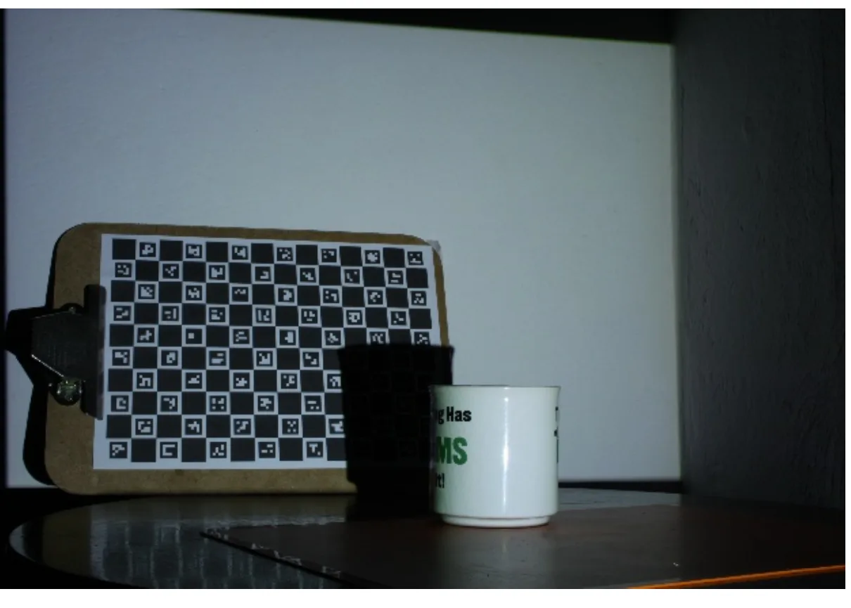
The repo’s own board (Fig. 6a): every other square carries a small black-bordered marker. This is one of the widget’s two bundled frames.
From contour to quad candidate
A raw contour is a dense pixel chain: one point per boundary pixel, so a few hundred
points for a modest marker. OpenCV’s detectMarkers reduces each one with approxPolyDP
(Douglas-Peucker) and keeps the ones that land on exactly four points within a shape
tolerance. board::hull_to_quad does something related but simpler: take the contour’s
convex hull, then repeatedly drop whichever hull vertex costs the least triangle area
(Visvalingam–Whyatt decimation) until four vertices remain.
fn hull_to_quad(hull: &[Pt]) -> Option<[Pt; 4]> {
    let mut poly = hull.to_vec();
    while poly.len() > 4 {
        // drop the vertex whose removal changes the polygon's area least
    }
    Some([poly[0], poly[1], poly[2], poly[3]])
}
Candidates are then kept if their perimeter falls inside
[min_perimeter_rate, max_perimeter_rate] × max(width, height): the same gate
minMarkerPerimeterRate / maxMarkerPerimeterRate set above, and the widget’s two
perimeter-rate sliders.
Per-quad homography, and bit sampling
Post 38’s report flags this module as directly reusable: a marker candidate is a
quadrilateral, a marker’s own bit grid is a canonical square, and mapping one onto the
other is exactly Zhang’s normalised DLT from
post 41 (zhang::homography).
So that’s what board::sample_and_decode calls, unmodified: the canonical
0..6 × 0..6 module square (a 4×4 code plus one module of black border each side) as
world, the candidate’s four ordered corners as image.
let world = vec![[0.0, 0.0], [n, 0.0], [n, n], [0.0, n]];   // n = 6 modules
let (h_mat, _cond) = homography(&world, &image, true, Solver::Jacobi)?;
With that homography, sampling is just projecting each of the 36 module centres through it and bilinearly reading the grey image there: no separate perspective-correction warp, because the homography is the perspective correction, evaluated only where it’s needed. A quick Otsu threshold over the 36 samples splits them into black/white; every one of the 24 border modules must come out black or the candidate is rejected outright (a real marker’s border is solid by construction; almost nothing else that survived the quad filter has one); the inner 4×4 becomes a 16-bit code.
The dictionary
DICT_4X4_250 is 250 sixteen-bit codewords, and the detector ships all of them.
Carrying the real dictionary is what lets the widget read the repo’s own historical photographs, which is the whole point. A decoder that only reads boards it printed itself is a decoder you can’t check against reality.
The codewords aren’t random. They’re chosen so that every code stays far from every
other under all four rotations, because a marker photographed upside down must still
resolve to one id and one orientation. For DICT_4X4_250 that minimum distance is 3,
and 3 is enough to make one-bit correction provable rather than merely usual. By the
triangle inequality, a word sitting within distance 1 of code and also within
distance 1 of a different code would put and within distance 2 of each other,
contradicting a minimum of 3. So a single flipped module always corrects to the right
code. That is exactly why OpenCV reports maxCorrectionBits = 1 for this dictionary, and
why decode accepts distance ≤ 1 and nothing else:
best.filter(|&(_, _, d)| d <= 1)What distance 3 does not buy is detection of a double flip. Two flipped modules can land at distance 1 from a different codeword, and then the decoder is confidently wrong. Walking all 30 000 two-bit corruptions of the 250 codes: 79.2% are rejected, and 20.8% decode to the wrong id. A test pins both numbers, because they are the sort of thing that quietly changes.
You can see where that 3 comes from, because OpenCV’s 4×4 dictionaries are one nested
family: DICT_4X4_50 is the first 50 codewords of DICT_4X4_250, which is itself the
first 250 of DICT_4X4_1000. Measure the minimum rotational distance of each prefix and
it degrades as the family grows: 4 at 50 codes, 3 by 100, still 3 at 250. There are
only 65 536 four-by-four patterns, each code claims four of them as rotations, and the
more ids you ask for the closer together they have to sit. This board needs 70 markers,
so it cannot use the 50-code prefix that would have kept distance 4: wanting seventy
distinguishable squares is what costs it double-flip detection.
Decode itself tries all four rotations of the sampled code against the dictionary’s
stored canonical orientation, so a marker read upside-down or on its side still resolves
to the right id: rotation in the result says how many quarter-turns it took, which is
also how the marker’s four corners get assigned consistently to “its” corner of the
checkerboard square around it.
Interior corners: local, not global
The last step is the actual payoff for occlusion tolerance, so it’s worth being precise about the design choice. A tempting shortcut is: fit one homography for the whole board from every detected marker corner, then project every interior checkerboard corner through it. That would work, and would also mean a single distant, badly-decoded marker corner can drag every corner’s estimate off, and a board only half in frame gets no corners at all until enough markers are visible to make the global fit stable.
board::interpolate_corners does the local thing instead, closer to what
interpolateCornersCharuco actually promises: every decoded marker proposes only the
four checkerboard corners of its own 20 mm square, by extrapolating its own already-fit
per-marker homography a little past the 14 mm footprint it was measured on:
let margin_mod = margin / module_mm;              // (20 - 14) / 2 mm, in module units
let local_corners = [(-margin_mod, -margin_mod), (n + margin_mod, -margin_mod), ...];
An interior corner shared by up to four neighbouring squares gets an average of however
many of those squares’ markers actually decoded: one proposal is enough to place it, and
a corner nowhere near any decoded marker is reported as not found, rather than
guessed at from the far side of the board. Every proposal then gets pulled onto the
nearest strong saddle response within a few pixels, reusing image::Hessian from post 38
exactly as it’s used there:
let resp = hess.lambda1[idx].min(-hess.lambda2[idx]);
if resp > best.2 { best = (x, y, resp); }
This mirrors what OpenCV’s own corner interpolation does, refining a geometric estimate onto the image’s actual local structure, without reusing its code, and it’s the piece that makes “cover half the board” a story the widget can actually show rather than just claim.
Results
Two tests matter here, and they ask different questions.
The first is whether the pipeline is correct in absolute terms, which needs a board
whose true geometry is known independently. So: a board generated by OpenCV itself,
CharucoBoard((10, 14), 20.0, 14.0, DICT_4X4_250), the exact call BoardInfo.py makes,
rendered straight-on, where every interior corner sits at a known pixel.
The second is whether it reads the real thing: two photographs of the physical board the structured-light rig was actually calibrated with, printed years ago from the same dictionary, and photographed under projector light with objects sitting on them.
The gap between those two photos is the real result, and it isn’t a decode failure. It’s a resolution one. In the clipboard frame the board is far enough away that a marker module is barely two pixels, and the adaptive threshold can’t hold a 6×6 grid together at that scale. Widen the window and it gets worse, not better: at the 23 px window that looked reasonable on the other frame, the same photo drops to 28 markers. That’s the whole argument for the window slider being exposed at all.
The widget
Five stages, live: greyscale, the adaptive threshold, every raw Suzuki–Abe contour, the quads that survived the perimeter filter (accent-coloured if they went on to decode), and one decoded marker’s unwarped 6×6 module grid. The default “detected” view overlays every decoded marker’s id on its quad and a cross on every interior corner it could place.
With JavaScript on, this becomes a live ChArUco detector: two bundled real photos, a file picker, and a camera button. Step through greyscale, adaptive threshold, candidate contours, surviving quads and an individual marker’s bit grid, with window-size and perimeter-rate sliders live. The detection downloads as JSON, and a “print this board” link serves the exact geometry above as an A4 PDF.
Things worth trying:
- Print the board and photograph it. The link below serves the real geometry, in the
real dictionary, so your printout is readable both here and by
cv2.aruco, and a photo of your own is the only way to see how fast the readout falls off with angle and distance. - Watch the “quads” stage on a real photo. Hundreds of candidates, almost none of them anywhere near a real marker: table grain, mug lettering, cardboard texture all produce quad-shaped hulls that the perimeter filter alone can’t rule out. Decode is doing real work rejecting them.
- Push the threshold window very small or very large on
sample-board-2.webp, where the statue’s shadow crosses part of the board. A window too small starts thresholding the board’s own print against itself; too large stops separating the shadow from the fully-lit squares next to it. - Cover part of the printed board with a hand before photographing it, then load that photo. Markers elsewhere on the board still decode, and the corners nearest your hand are the only ones reported missing: that’s the entire pitch for a ChArUco board over a plain one, made concrete.
Output format, for the next post
Post 61 takes a pile of (board point, image
point) pairs and fits a camera matrix from them: it needs this post’s output, not this
post’s pixels. Post 38 already ships a checkerboard-corners output format, version 1: a
flat, always-fully-populated row-major array of [x, y] pairs, because the Liu detector
either finds the whole board or refuses outright. A ChArUco board can genuinely succeed
partially, so this post’s format, finding-a-checkerboard version 1, keeps the same
row-major interior-grid shape but allows null where occlusion or a failed decode left a
corner unplaced:
{
  "format": "finding-a-checkerboard/v1",
  "board": { "colsBlocks": 10, "rowsBlocks": 14, "squareMm": 20, "markerMm": 14 },
  "markers": [{ "id": 0, "rotation": 0, "corners": [[x, y], [x, y], [x, y], [x, y]] }],
  "corners": {
    "rows": 13, "cols": 9,
    "order": "row-major; corner k is column k % cols, row floor(k / cols); null if unplaced",
    "points": [[x, y], null, "…"]
  }
}
corners.points is the part a calibration solver actually wants: same row-major
convention as the checkerboard-corners format, just with holes it has to be prepared to skip.
markers is kept alongside it for anyone who wants the raw marker reads (ids, rotation,
quad corners) rather than only the interpolated grid.
What this doesn’t do
- No multi-window adaptive threshold. OpenCV pools candidates across a whole ladder of window sizes (3 to 50, step 2); this thresholds once, at whatever the slider says.
- No true 30 fps live decode. The camera button freezes one frame and runs the detector on the still, the same choice post 38’s widget makes: a single-threaded WASM contour tracer over a full camera frame every animation frame is a real cost this post didn’t spend the budget to hide.
- No lens distortion, no extrinsics. Same limits post 38 already flagged for the plain-checkerboard detector: this post only finds and identifies corners; post 61 is where a camera matrix comes from them.